Workpiece & target
Define material, allowance and acceptance criteria before choosing the abrasive or geometry.

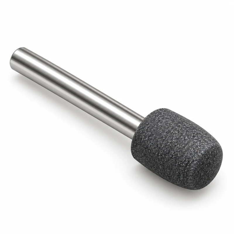
Profiled tools for controlled grinding of curved raceway features.
APPLICATION REFERENCE / HM-G18
Application reference, not a stock SKU. Configuration and supply require technical review.
CV-joint components; internal and external raceway features.
Coordinate tool profile, spindle connection and CNC trajectory to the actual component.
CV-joint raceway grinding combines a formed surface with a controlled trajectory. Identify the raceway model, local radius, spindle connection and collision envelope.
Define material, allowance and acceptance criteria before choosing the abrasive or geometry.
Review mounting, access and process motion against the actual machine arrangement.
Agree the drawing and evaluation method before comparing finish, wear or process capability.
| Configuration item | Information to provide / confirm |
|---|---|
| Application-specific inputs | Raceway model; local radius; shank or thread; collision envelope. |
| Workpiece | Material designation, hardness, heat treatment and incoming stock |
| Acceptance criteria | Drawing tolerances, form requirements, surface texture and measurement method |
| Wheel & mounting | Shape drawing; outside diameter D, width T, bore H or shank/thread connection, as applicable |
| Abrasive system | Workpiece-dependent abrasive, grain specification, bond and conditioning method |
| Machine & process | Spindle/interface, coolant, dressing arrangement and approved operating limits |
| Quantity & supply | Trial / production quantity; final configuration and availability confirmed after review |
HM-H and HM-G references identify this application collection, not inventory SKUs. Dimensions, construction, supply feasibility and lead time require confirmation.
Send a workpiece and tool drawing where available, material and hardness, machine and interface, stock allowance, finish, tolerance, coolant and quantity.
No. Images are AI-generated family illustrations. Geometry, colors and proportions are indicative; the approved drawing defines the actual tool.
Provide the actual machine model, mounting interface, spindle or feed arrangement and available clearance. A machine brand alone does not establish compatibility.
Specification and acceptance requirements are agreed for the application. Operating speed follows the approved design and actual tool marking; an illustration is not an operating instruction.
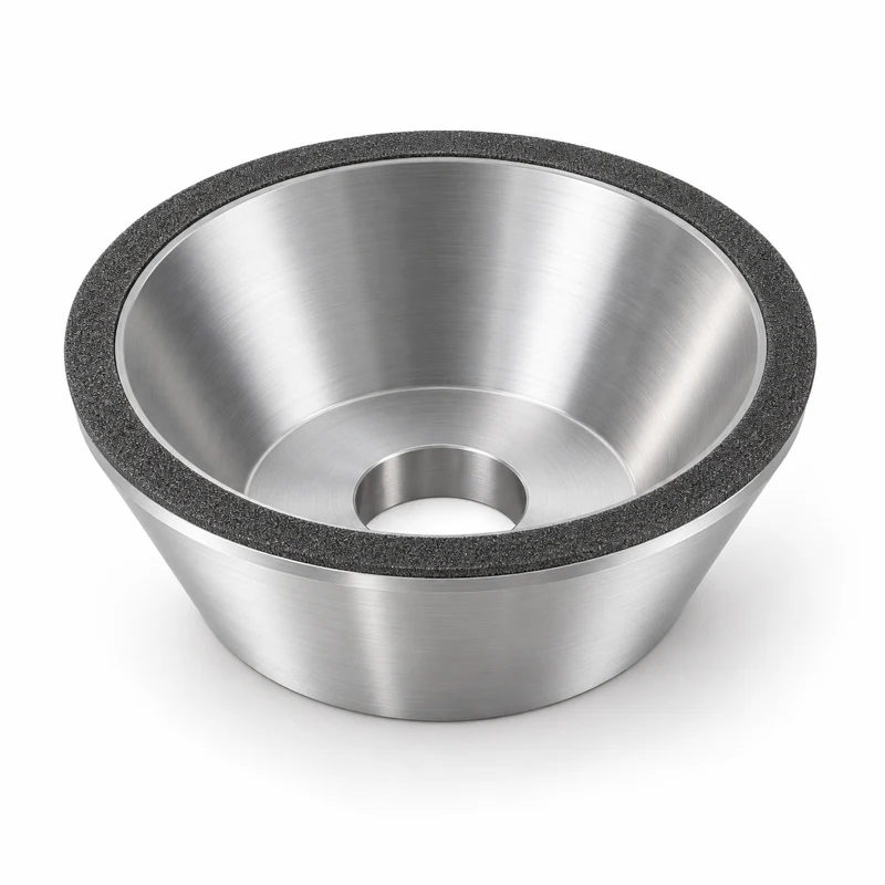
HM-G09 / GRINDING
Cup-form grinding concepts for bevel gears with geometry defined by the machine and tooth system.
View Application & Configuration →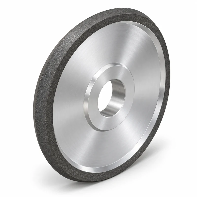
HM-G10 / GRINDING
Profile-wheel concepts for gear teeth, splines and related form-ground components.
View Application & Configuration →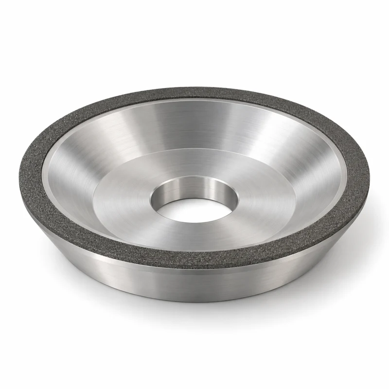
HM-G11 / GRINDING
Face-grinding wheel concepts for new-tool production and controlled resharpening.
View Application & Configuration →