HM-H01 / HONING
Horizontal Honing Mandrels
For controlled finishing of bores with a compact mandrel and an expandable abrasive contact.
View Application & Configuration →
Choose an application. Match the workpiece. Define the configuration.
Explore grinding and honing application profiles, from tool manufacturing and precision grinding to bore finishing.
Browse ApplicationsGet Application SupportApplication-led configurations · Drawing-based technical review
Search by application, reference or workpiece, then review the configuration requirements.
No matching applications. Try another term or send your drawing for review.
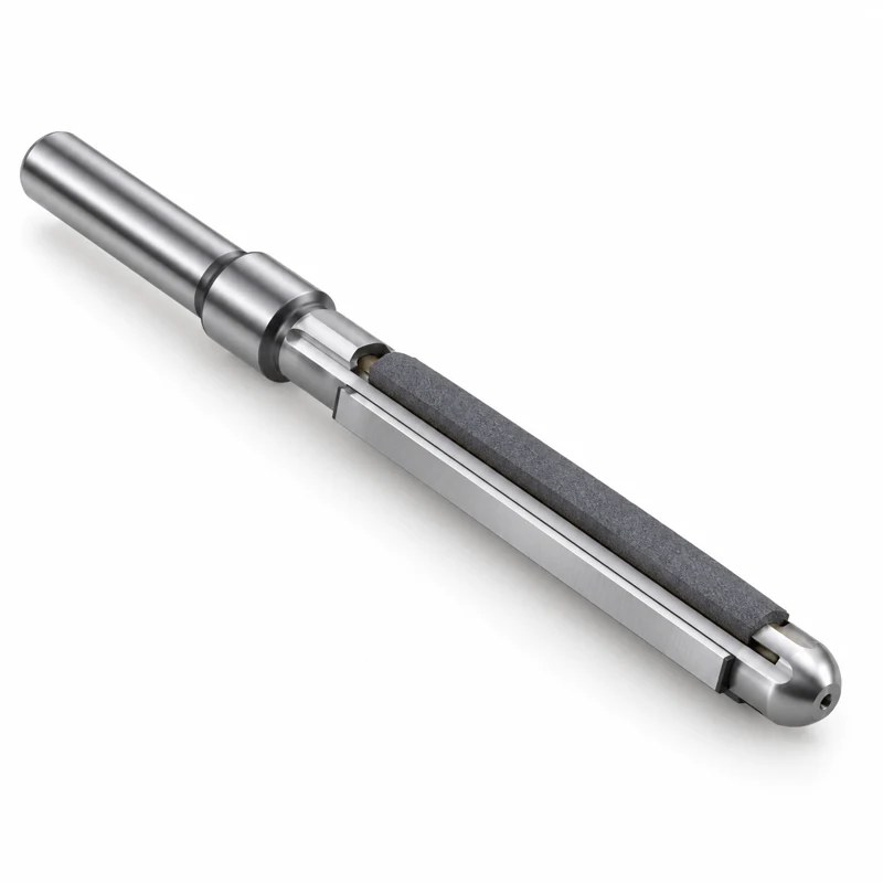
HM-H01 / HONING
For controlled finishing of bores with a compact mandrel and an expandable abrasive contact.
View Application & Configuration →HM-H02 / HONING
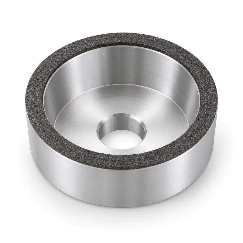
Slender honing concepts for small bores where tool access and support are critical.
View Application & Configuration →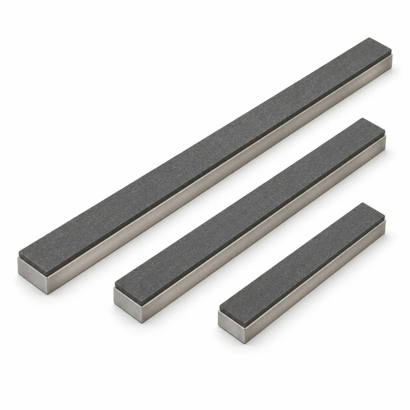
HM-H03 / HONING
Diamond or CBN stone configurations for application-specific bore finishing.
View Application & Configuration →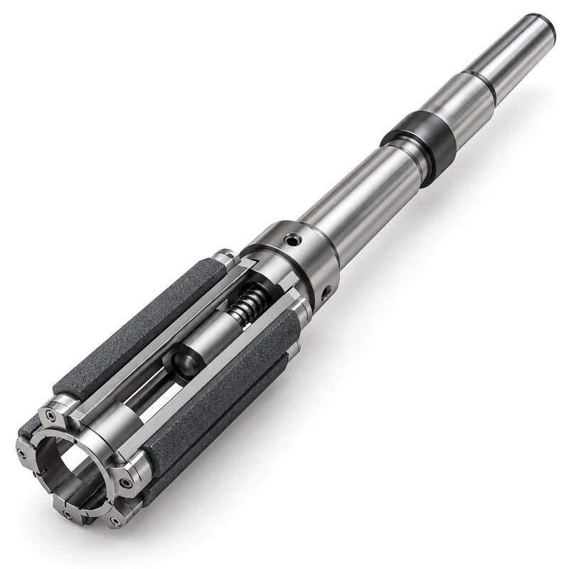
HM-H04 / HONING
Multi-stone contact for supported honing of medium and larger bores.
View Application & Configuration →HM-H05 / HONING
Replaceable abrasive elements selected around the workpiece and the honing platform.
View Application & Configuration →HM-H06 / HONING
Vertical honing configurations for bore size, form and surface-finish control.
View Application & Configuration →HM-H07 / HONING
A sequence of preset abrasive tools develops bore size and finish in staged passes.
View Application & Configuration →HM-H08 / HONING
Head concepts for coordinated rough and finish honing on compatible machines.
View Application & Configuration →HM-H09 / HONING
Stone selection for staged engine bore and cylinder-liner finishing.
View Application & Configuration →HM-H10 / HONING
Staged abrasive finishing to develop a plateau surface while retaining the specified valley structure.
View Application & Configuration →HM-H11 / HONING
Guided tooling concepts for aligned engine bores and related long-bore finishing.
View Application & Configuration →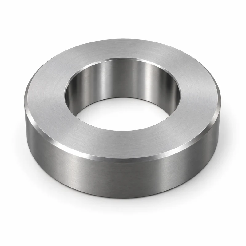
HM-H12 / HONING
Setting-ring concepts for establishing a reference in compatible bore-gauging systems.
View Application & Configuration →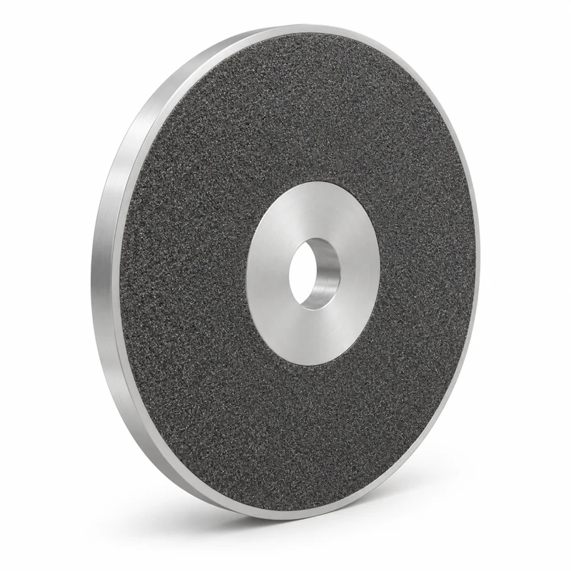
HM-G01 / GRINDING
Abrasive face-wheel concepts for controlling opposing faces in production grinding.
View Application & Configuration →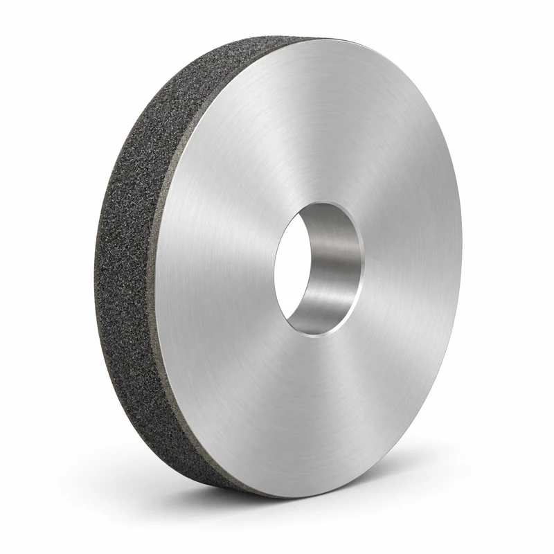
HM-G02 / GRINDING
Vitrified CBN configurations for compatible hardened ferrous camshaft grinding applications.
View Application & Configuration →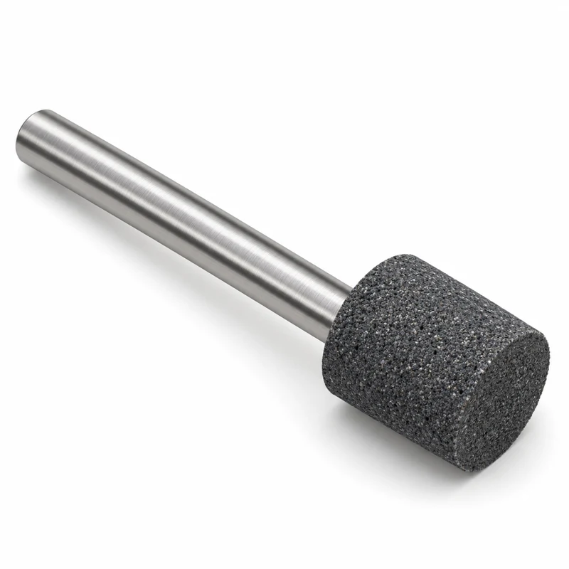
HM-G03 / GRINDING
Compact abrasive tools for bore access, form control and internal surface finishing.
View Application & Configuration →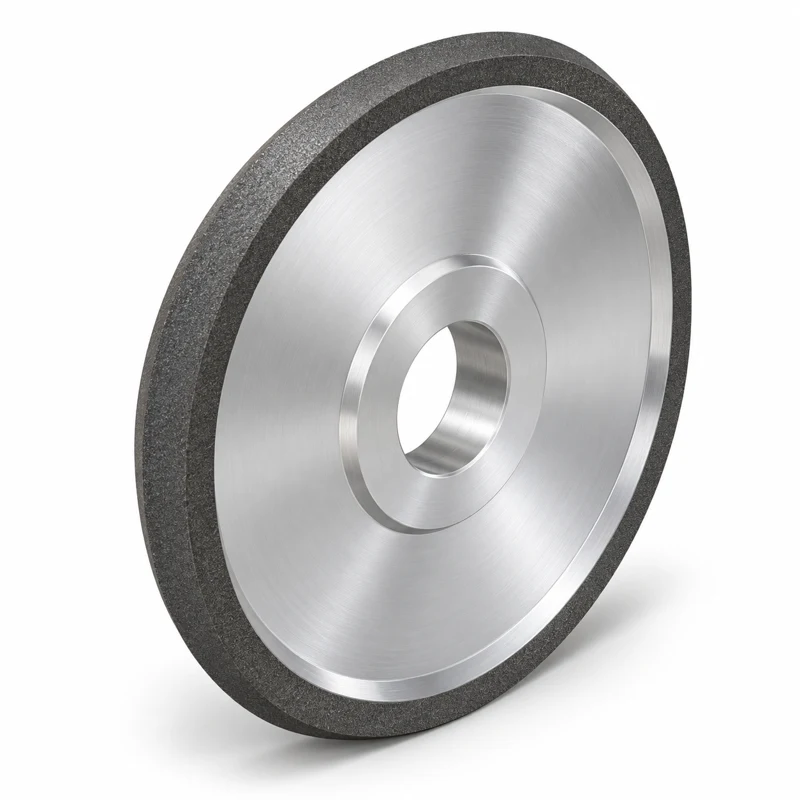
HM-G04 / GRINDING
Peripheral wheel concepts for tool flutes, gashes and related stock-removal operations.
View Application & Configuration →HM-G05 / GRINDING
Diamond-wheel configurations for finishing superhard insert peripheries and clearances.
View Application & Configuration →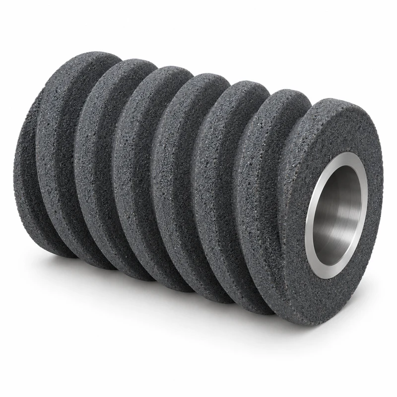
HM-G06 / GRINDING
An application pathway for continuous generating gear grinding, requiring a defined abrasive system.
View Application & Configuration →HM-G07 / GRINDING
Material-led wheel selection for external diameters, shoulders and related surfaces.
View Application & Configuration →HM-G08 / GRINDING
A process-led route to matching small wheel forms and the workpiece material system.
View Application & Configuration →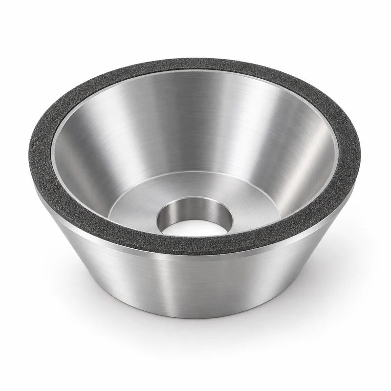
HM-G09 / GRINDING
Cup-form grinding concepts for bevel gears with geometry defined by the machine and tooth system.
View Application & Configuration →HM-G10 / GRINDING
Profile-wheel concepts for gear teeth, splines and related form-ground components.
View Application & Configuration →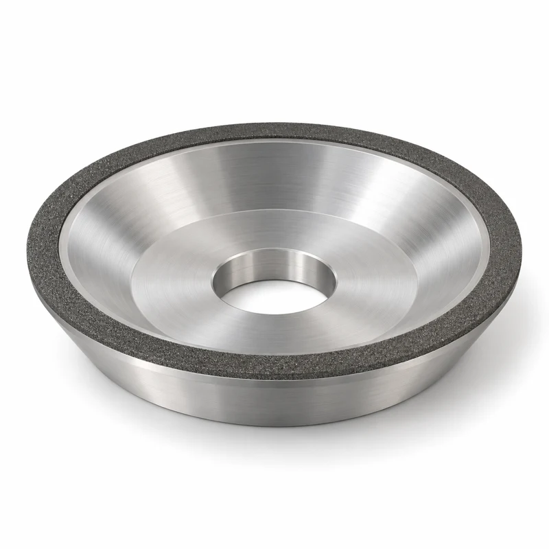
HM-G11 / GRINDING
Face-grinding wheel concepts for new-tool production and controlled resharpening.
View Application & Configuration →HM-G12 / GRINDING
Diamond wheel configurations for insert peripheries, radii and relief surfaces.
View Application & Configuration →HM-G13 / GRINDING
Face and angled wheel forms for cutting-tool clearances and end geometries.
View Application & Configuration →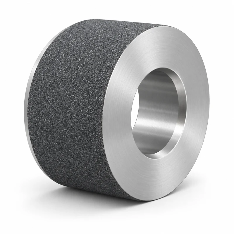
HM-G14 / GRINDING
Wheel concepts for supported bar and pin grinding, from stock removal to finishing.
View Application & Configuration →HM-G15 / GRINDING
CBN profile-wheel concepts for suitable hardened ferrous gear components.
View Application & Configuration →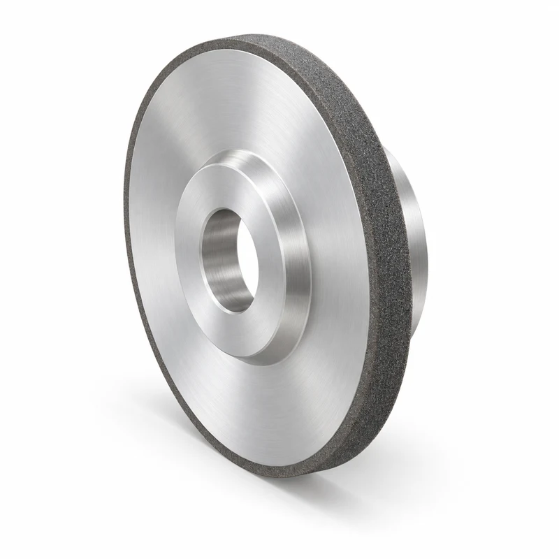
HM-G16 / GRINDING
Peripheral-wheel configurations for hardened diameters, shoulders and formed external surfaces.
View Application & Configuration →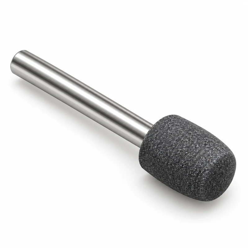
HM-G17 / GRINDING
Formed abrasive tools for application-specific curved internal and external tracks.
View Application & Configuration →HM-G18 / GRINDING
Profiled tools for controlled grinding of curved raceway features.
View Application & Configuration →HM-G19 / GRINDING
CBN wheel concepts for production grinding of compatible hardened steel parts.
View Application & Configuration →HM-G20 / GRINDING
Narrow peripheral abrasive forms for slots where width and straightness matter.
View Application & Configuration →HM-G21 / GRINDING
Vitrified CBN concepts for compatible hardened crankshaft journal and shoulder applications.
View Application & Configuration →HM-G22 / GRINDING
Profile-wheel concepts for developing and maintaining hob tooth geometries.
View Application & Configuration →Define the feature, material, wheel envelope, interface, coolant and dressing method.
Define bore geometry, stock, form and surface texture. Match the tool to the feed, stroke and measuring arrangement.
Use the reference to start the discussion. Final geometry, supply and operating limits follow the agreed specification.
Shared images illustrate tool families. HM-H and HM-G references are collection indexes, not stock model numbers.
HM-H and HM-G references identify this application collection, not inventory SKUs. Dimensions, construction, supply feasibility and lead time require confirmation.
Send a workpiece and tool drawing where available, material and hardness, machine and interface, stock allowance, finish, tolerance, coolant and quantity.
No. Images are AI-generated family illustrations. Geometry, colors and proportions are indicative; the approved drawing defines the actual tool.
Provide the actual machine model, mounting interface, spindle or feed arrangement and available clearance. A machine brand alone does not establish compatibility.
Specification and acceptance requirements are agreed for the application. Operating speed follows the approved design and actual tool marking; an illustration is not an operating instruction.